


History
2000
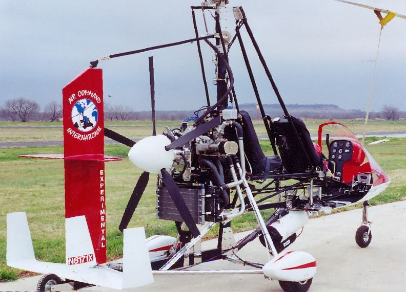
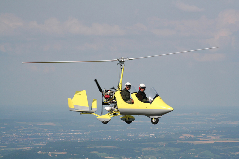
Gyro Recovery System from New Horizons Components
The simplest way to decrease the number of fatal gyroplane accidents is the use of a ballistic parachute. The one fatal gyro maneuver is the power push-over. The best option is not get into a power push-over. Gyro instructors teach their students how to avoid it. It is caused when negative-G allows rotor speed to decay. Rotor blades slow up, slam into the rudder or prop, and break them off. The controls won´t work; lift from rotorblades is gone. The gyro falls like a rock.
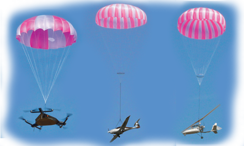
The ballistic parachute is mounted under the gyro so it fires backwards and to the side. With the gyro falling nose-first, a parachute firing backward is firing upward, relative to the ground. When the pilot pulls the engine down. The parachute deploys and inflates in 2,3 seconds.
The parachute bridle is attached to a latch near the right main wheel. With the gyro hanging under the parachute from the latch by its right wheel, rotorblades stop turning almost immediately.
The pilot pulls another handle to release the latch. The parachute pulls the bridle to near the top of the mast. The gyro re-orients itself to descend in an upright position, about 10 inches nose-down.
The tail if the gyro weathervanes downwind so the gyro is moving tail-first at touchdown. The nose gear of the gyro touches the ground first, and the gyro lands backwards.
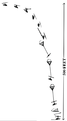
It takes about 500 feet of altitude to do a power push-over, deploy the ballistic, and descend. Pilots must fly no less than 500 feet above ground level. If you do this, you may survive the loss of rotor blades in a power push-over, structural failure, or mid-air collision. Thy Gyro Recovery Systém could save your life.
It takes about 500 feet of altitude to do a power push-over, deploy the ballistic, and descend. Pilots must fly no less than 500 feet above ground level. If you do this, you may survive the loss of rotor blades in a power push-over, structural failure, or mid-air collision. Thy Gyro Recovery Systém could save your life.
„Gyro Recovery system is the greatest safety advance for gyros since autorotation.“ Said the president of Popular Rotorcraft Association Chapter 007 in Dallas.
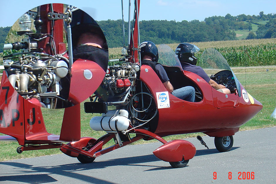
The inventor of the Gyro recovery system (GRS) with unit Galaxy GRS , Larry Neal, said he didn´t invent the GRS to make money; he did it to save lives. A close friend of his died in a power push-over in a gyro in 1998, and if he had a GRS on his gyro, Neal says he´d be alive today. While the GRS won´t save this man´s life, it could save yours.
The GRS is not just an idea. Neal said enough engineering has gone into his system to make it strong enough to be practical, cheap enough to be marketable, and simple enough to adapt to almost any gyro. New Horizons Components is putting them on Air Command International gyros now.
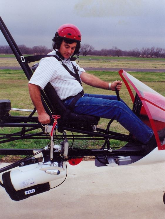
The parachute canister, bridle, and latch weight 25 pounds for a single-place gyro and 42 pounds for a two-place gyro. If you fly an ultralight single place gyro, 28 pounds of a parachute recovery system can be deducted in meeting your 254-pounds of maximum empty weight. Pilots will also need to use a four- or five-point harness instead of just a seatbelt. The harness is included as part of the Gyro Recovery System.
The GRS is an affordable life insurance policy. The GRS for a single-place gyro weighing less than 850 pounds with pilot and fuel is $2,700. The GRS for a two-place gyro weighing less than 1,275 pounds with pilot and fuel is $3,200. Shipping costs are not included. It should take about six weeks between receipt of an order and shipment to the customer.
The GRS has not been tested. The first person to test it will be the first who uses it in an emergency.
The GRS will be flown on gyros at Bensen Days, Sun´N Funm the PRA International Fly-In at Mentone, and EAA AirVenture at Oshkosh.
Why is it necessary to talk about „Custom-Fitting the Gyro recovery Systém to Your Gyro?“ Gyros vary so greatly that your gyro is probably unique! While it may be similar to other gyros, your gyro may have some unique features that make a „standard mount“ for Gyro recovery Systém impractical. Each Gyro Recovery System must be matched to the specific gyro on which it will be flown.
The ballistic parachute is mounted on the gyro so it fires backwards and towards the right side. With the gyro falling nose-first, a parachute firing backward is firing upward, relative to the ground. If you have an Air Command, Bensen or similar gyro with less than 2-foot clearance between the keel and the ground, you will need to mount the ballistic parachute module on the top of the right axle.
If you have a Dominator, Air Command Elite, or similar gyro with more than 2-foot clearance between the keel ant the ground, you may mount the ballistic parachute (A) beneath the front keel tube.
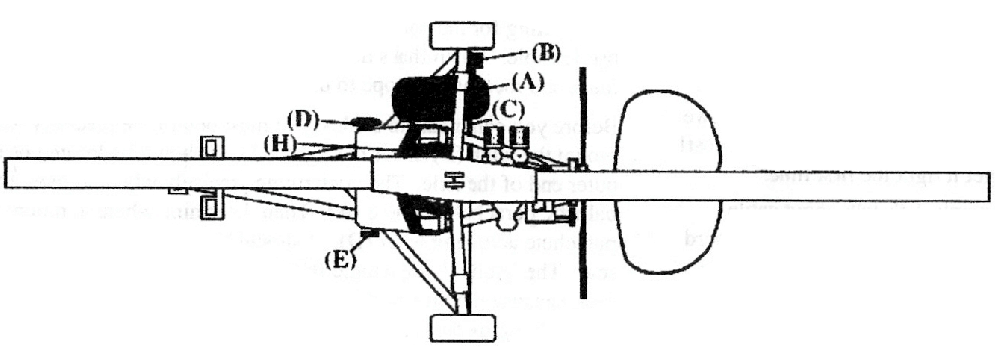
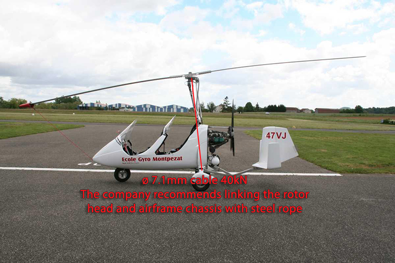
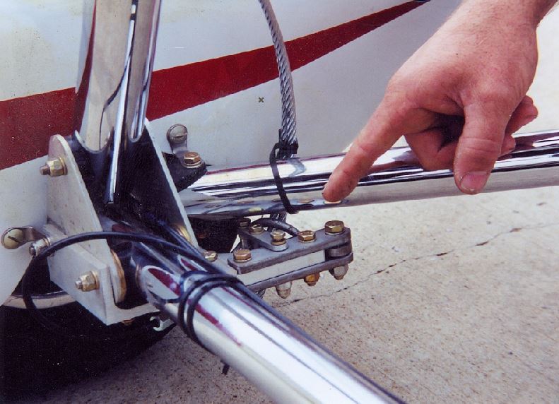
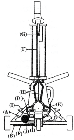
The parachute bridle is attached to a latch (B) near the right main wheel. If there is any possibility that the shock of the parachute opening could pull the axle off your gyro, you will need a cable (C) from the latch that loops around your keel tube. The latch itself attaches on the bottom of the right axle tube.
The pilot pulls a lever (D) to deploy the ballistic parachute. It shuts the engine down. The pilot then pulls another handle (E) to release the latch. The parachute pulls the bridle (F) to near the top of the mast. It hangs from the attachement to the mast (G). The pilot is held into the gyro with a four-point suspension harness (H) that is attached to the airframe at four points. The harness comes as a part of the Gyro Recovery System.
As you can see, many of the parts of the Gyro Recovery System must be mounted at specific locations on the gyro. Except for the 2 inch square mast and square rear keel, all tubing on a single-place Air Command Commander is round. Different mounting hardware is needed for round tubing than for square tubing. When the parachute is deployed, the bridle or parachute cable is violently jerked. The cable must be routed with care and with no sharp bends. This means that the correct length of cable is needed – not too long, not too short. The cable will normally be secured to the airframe with wire-ties, which pop off on deployment.
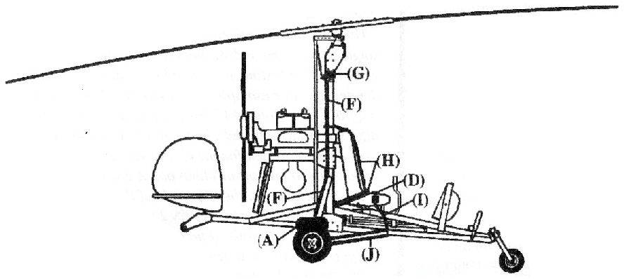
Looking at the gyro on the Right Side View, you can see the lever (D) that deploys the parachute, through the cable (I) from the actuating lever to the ballistic parachute module (A). In the Front View, the handle (E) releases the latch (B), through the cable (J) that goes from the latch release handle to the latch. The long cable (F) goes from the main attach point on the mast (G) down to the latch (B), then back to the ballistic parachute module (A). The four point suspension harness (H) is attached to the airframe.
When the parachute deploys, it will pull the parachute bridle cable (F) through a steel ring in the latch (B). The cable (F) will snap taut between the latch (B) and the main attach point on the mast (G). When the parachute inflates, the gyro will be hanging from the latch (B). Pull the latch release handle (E), and the latch releases the bridle cable (F). it snaps taut, and the gyro falls to an upright position suspended from the main cable attach point (G) on the mast. The parachute bridle cable (F) must be routed so the cable pulls only on the latch (B) and the main attach point to the mast (G). You must pay attention, when routing the cable, to how it will pull off the airframe when deployed. You do not want the cable to be looped around your axle, axle support tubes, mast, or any other airframe parts. The cable should not make any bends with a diameter less than 4 inches.
Before you can measure cables, you must determine precisely where to mount the latch (B) under the right axle. It should be located near the outer end of the axle. Then determine precisely where to mount the ballistic parachute module (A). Then determine where to mount the parachute actuating lever (D). It should be on the right side of the pilot seat. The latch release handle (E) should be on the left side of the pilot seat, because the pilot will be able to reach the handle better when the gyro is hanging from the latch (B) on the right axle.
Cable (F): Main attach point on mast (G) to latch (B) to ballistic parachute module (A). From main cable attach point on the mast (G), run rope upward and make a 4-inch diameter loop before coming back down the rear of the mast. Run the rope down to the keel and through the steel loop in the latch (B). Run the rope from the steel loop in the latch (B) along the airframe to the carabiner at the back of the ballistic parachute module.
GRS contains the electrical motor disconnectors.
©2000 New Horizons Components, Inc.
2006
Next step attachment rope loop on the frame Gyro above the center of gravity in the place seats and engine. Draining latch point B on the chassis.
2010

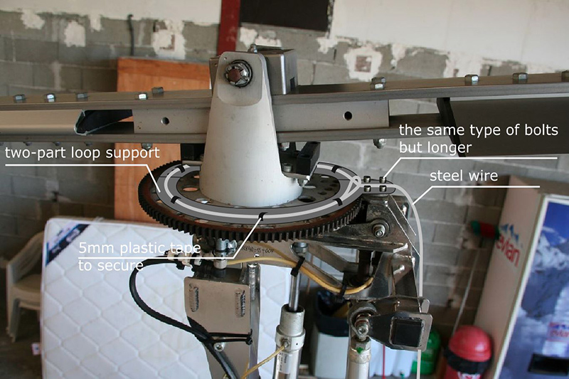
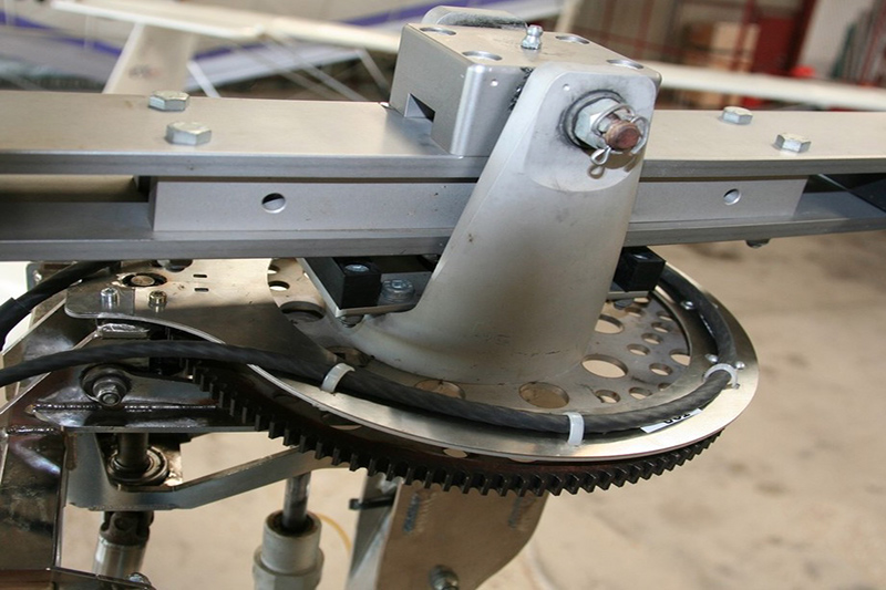
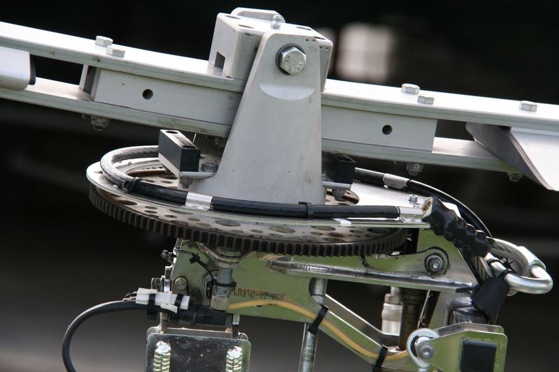
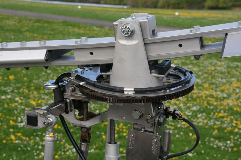
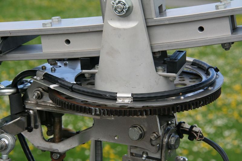
2011-2012 Spring
Moving rope loop on the auxiliary frame above spin gear of rotor. Fixing the rope with plastic handles + steel security self-locking sleeves.